Mobile robotics in simulation with ROS 2 - Part 2: Perception
Introduction
Part 1 ended on two images from the robot's camera. In one of them, a large marker on a nearby post and another on the box were plainly visible and went unread, while a tiny one at the far end of the room was read. This part builds the robot's perception and explains why it misses some ArUco markers.
The subject is the ROS 2 node that detects markers in real time:
- How it turns an image into each marker's position.
- How it reads each one.
- How far what it measures can be trusted.
The question behind this part is: how far away can the robot read a marker, and how well does it know where that marker is?
The chosen architecture
The detector has its own ROS 2 package, aruco_detector. From the camera it takes two things: the image and its calibration, which says how to go from pixels to metres. For every image it publishes the list of markers it found, with each one's id, position and orientation relative to the camera, along with the image with every marker outlined and a drawing of each one for RViz.
The node knows nothing about the simulation. With a real camera, it only needs its two topics connected. The core of the detector reads the markers and works out their position, and it has no ROS 2 dependency either. That lets its tests render a marker at a chosen distance and angle and check that the detector recovers that pose.
How a marker is read
Reading an ArUco marker takes five steps, the same ones as in the diagram:
- The image goes to black and white. Each pixel is compared with the average of its neighbours, which keeps a shadow from passing for the marker's black.
- Four-sided outlines are found. At first, every one of them is a candidate marker.
- Each candidate is straightened out, removing the perspective, and split into a grid of 6 by 6 cells. The outer cells make a black border, and the 16 inside hold the code.
- Each cell is read as black or white. The 16 bits make a code that is looked up among the 50 in the
DICT_4X4_50dictionary. - From the four corners, refined to fractions of a pixel, and the marker's real size (15 cm), the detector works out where the marker is and which way it faces.
The important part, where a marker gets read or lost, is step 4.
Decision 1: how is each cell read?
The robot's camera is 640 by 480 pixels. A 15 cm marker 4 m away spans about 21 pixels, and each of its six cells is around 3.5 pixels wide. At that size, the edge of each cell blends into the next one.
PIXELS_PER_CELL = 6
CELL_MARGIN = 0.34  # 2 of the 6 px: int(0.34 * 6) is 2, where 1/3 would round down to 1

parameters.perspectiveRemovePixelPerCell = PIXELS_PER_CELL
parameters.perspectiveRemoveIgnoredMarginPerCell = CELL_MARGIN
The result
These are the same two images from Part 1, now read from the middle of each cell:
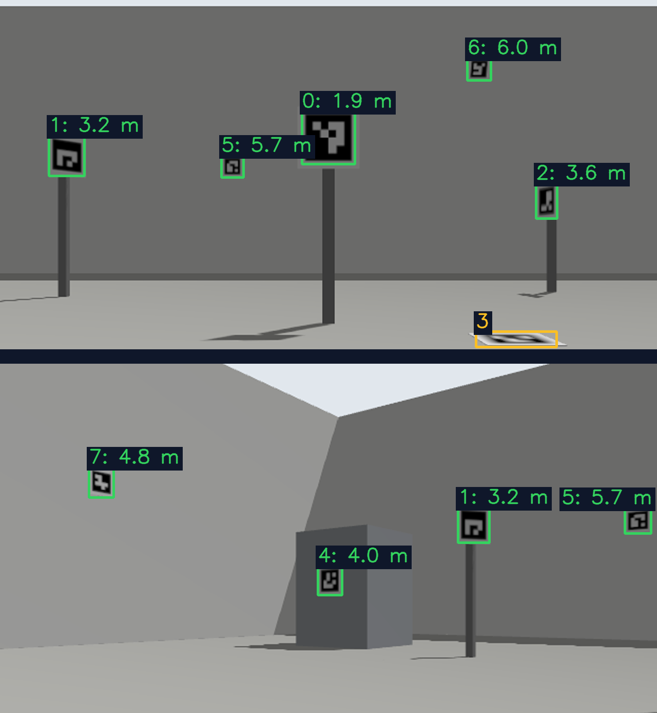
At the top, five of the six markers in view are read. The one on the floor, seen almost edge-on, still is not. At the bottom, all four are read, the one on the nearby post (1) and the one on the box (4) included.
Two images are still not enough to make a decision. An experiment placed the robot at 216 points across the room, half a metre apart, and turned it to 12 headings at each one: 2,592 images in all. Gazebo's true pose tells which markers are in view in each image, and every image is read both ways. For markers within 45° of head-on:
| Distance | Whole cell | Middle of the cell |
|---|---|---|
| 2 to 3 m | 98% | 100% |
| 3 to 4 m | 66% | 98% |
| 4 to 5 m | 37% | 91% |
| 5 to 6 m | 30% | 77% |
Across the 2,592 images, no marker was ever mistaken for another.
This gives a rule that holds for any camera and any marker size, because what counts is how many pixels each cell spans:
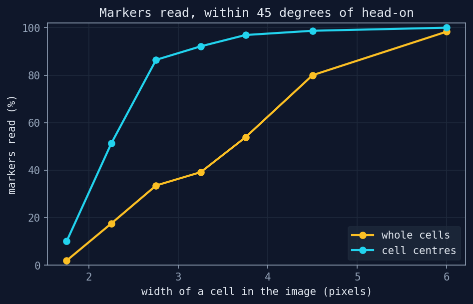
Reading whole cells, a cell needs about 5 pixels for nearly every marker to be read. Reading their middle, about 3.5 is enough. With this camera and 15 cm markers, that takes the reliable range from about 2.8 m to about 4 m.
Decision 2: how far can a measurement be trusted?
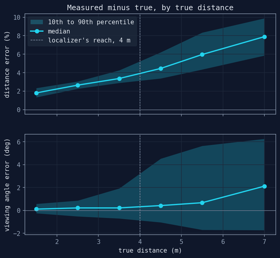
Besides reading the marker, what matters is how well its position is measured. To find out, every reading is checked against the true distance and angle from Gazebo:
| Distance | Distance error (median) | Angle error (80% of readings) |
|---|---|---|
| 1 to 2 m | +1.8% | -0.2° to +0.6° |
| 2 to 3 m | +2.6% | -0.5° to +0.9° |
| 3 to 4 m | +3.4% | -0.7° to +1.9° |
| 4 to 5 m | +4.5% | -1.0° to +4.5° |
| 5 to 6 m | +6.0% | -1.7° to +5.6° |
Distances come out slightly long, and more so the further away the marker is. Up to 4 m, the median distance error stays at 3.4% or less, about 14 cm at 4 m, and 80% of the angles stay within about 2°. Past that they grow: from 4 to 5 m, 80% of the angles already spread to 4.5°, more than double.
| Option | What it means |
|---|---|
| Use everything that is read | more measurements, some of them with angles 5° off or worse |
| Use only markers closer than 4 m | fewer measurements, with a median error of 3.4% or less |
| Use them all, weighted by distance | relies on the weight keeping up with an angle error that doubles past 4 m |
The robot will use these measurements to work out where it is in the room. So the localizer in Part 4 only takes markers closer than 4 m, and within that range it trusts the farther ones less.
Limitations
- Clean images under the same light. No sensor noise, no motion blur, no lens distortion. In the real world the camera will read worse, and the rule will shift.
- The measured distance comes out slightly long, more so for far markers. Subtracting that bias would tune the detector to Gazebo, and correcting it will take a real camera with its own calibration.
- One misread bit will still drop the marker. That is how the process works with
DICT_4X4_50, and markers whose cells are 2 pixels wide are read only some of the time. - Everything is ideal in simulation. In a real place, with textures and signs, the dictionary runs the risk of detecting a marker where there is none.
Wrapping up
The robot now reads markers in real time and knows where they are. Reading the middle of each cell takes the reliable range from about 2.8 m to about 4 m without changing a single marker, and the measured accuracy is why the robot will only locate itself from markers closer than 4 m.
Coming up in Part 3
Safety: a 2D lidar and a node that stands between whoever drives and the wheels, where it can stop the robot before it hits something.
The full code can be found at github.com/KevDP/ros2-aruco-world. To regenerate this part's numbers:
experiments/sim.sh -- python3 experiments/perception.py
python3 experiments/perception_report.py
experiments/sim.sh -- python3 experiments/camera_views.py